PiCar
A client-server application for interfacing with a remote RPi robot to control it or to find objects autonomously.
Main Features
Taking inspiration from lab 3, we realized that using the PiTFt buttons and the breadboard buttons were not very practical for controlling the robot as it moves around; therefore, we look into solutions that will be wireless. We talked about how we can remedy this issue by creating a remote controller that will allow the user to control the robot. We wanted something that works even when the user is not directly next to or even can see the robot - something that matches the social-distancing semester we are having. As a result, we came up with the idea of a PiCar Controller which is a system that is composed of a RPi car that is controlled via https requests. Another feature we think that will be necessary is a live feed of what the robot is looking at, which can be achieved with a PiCamera. Depending on the progress, we may add other features such as recording previous actions and displaying some status on the PiTFT to inform those around the RPi what instructions are running.
Objective
This project is based on lab 3 where the robot platform developed in that lab planned to be reused with added functionality/components. Externally, image sensors (quality resolution undetermined as of now) will be placed around the robot with images of its surroundings being constantly taken and ‘analyze’ to compare whether the object in question is there. One of them will be used as a live feed of the robot’s view. This project will have two modes: remote-control and autonomous. Remote Control is where the user has full control of the robot’s movements and while the user is driving the robot, is immediately alerted when the object has been identified through a live feed. Autonomous mode will leave the moment entirely up to the robot (by an algorithm developed by both team members). When the object has been identified, the robot will stop moving, face the direction of the object and emit a sound indicating that it has found the object. It is also planned to include LEDs to the raspberry pi to indicate the status of the recovery robot.
Design and Testing
Software
Interface Scripts
We have decided to build two main scripts as entry points to launching PiCar, one to launch the PiCar server and the other to authenticate the client. These scripts' roles are to: start the Flask webserver and make sure ssh tunneling is established between the server and the client ports through the class' server. Since both students were working remotely, we relied on the class' public IP to do port forawrding (ssh tunneling).
- Server.sh: Starting point for launching PiCar website and creating ssh tunneling ports.
- Client.sh: Allowing the user to forward requests through ssh tunneling.
- Clean.sh: Freeing any used PiCar ports for the user to use.

The first main script -- server.sh -- sets up the website and creates a port on the class' public server in order to do ssh tunneling to give authenticated remote users access to the website.
Regarding the ssh tunneling, the server exposes two ports (port=8888 and port=9999) (as show in figure 1) by creating a connection on two remote ports (port=8888 and port=9999 respectively). On the server RPi, we have two servers running. These two ports exposes the camera server and the website server. We seperated these into two servers in order for us to create different processes and allow multi-process systems that can provide a smooth real time video feedback system for remote control mode. From these two port connections, any authenticated users sending requests from the class' server will be able to access the RPi's website and camera.

The second main script -- client.sh -- has only one job which is to allow the user to forward any localhost requests to the class' server ports. In order for us to switch roles as servers and clients, we decided to create four ports on the class' server. Since each student has their own RPis and camera, we were able to control each others robots through ssh tunneling.
Regarding the ssh tunneling, the server exposes two ports -- port=8888 and port=9999 -- (as show in figure 2) by creating a connection on two remote ports (port=8888 and port=9999 respectively). From these two port connections, any remote clients can access the server RPi.
The last script -- clean.sh -- was created to allow the user to kill and free any ports that PiCar will need before running client.sh or server.sh. This has made development super fast since we relied on an automated way to free ports. One other option that we looked into is adding input parameters to these scripts to allow the user to change these ports. Since this is a prototype, we did not see the value of adding such support at this time.
KEY POINTS on ssh tunneling:
- To have a successful connection, the client HASH to connect to the same ports as the server namely port=8888 and port=9999 in order to access RPi server's website and camera.
- To avoid any conflicts with port on the class' server, a new server needs to create new ports (instead of port=8888 and port=9999 ).
- To stop the ssh tunnel from "HANGING UP", add "-fNR or -fNL" to put keep these connections in background and free the RPi's shell.
Web Server
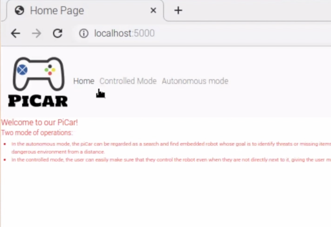
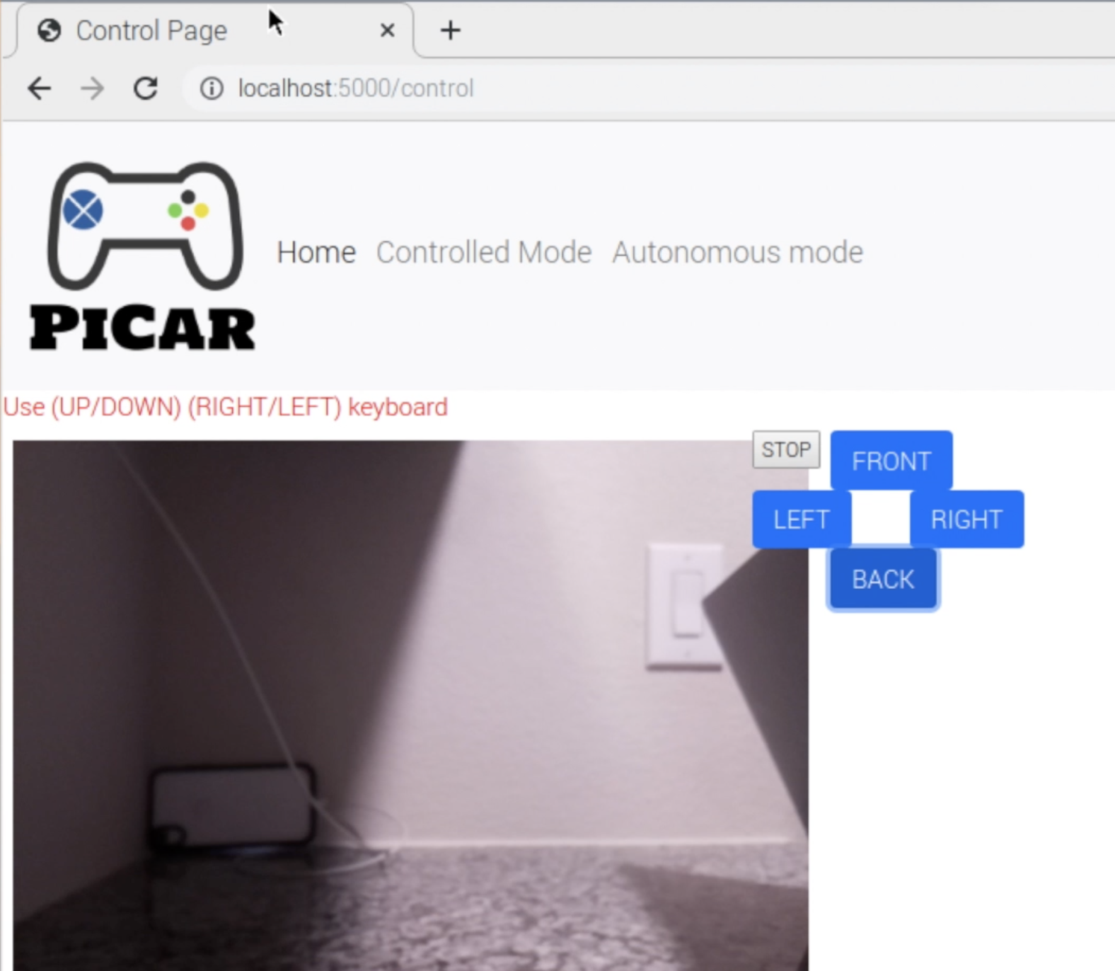
The web server uses python Flask app for the backend and relies on CSS, HTML, Jquery, and JS for the frontend. The frontend has 3 main pages: home, control, and autonomous as shown below.
To connect these pages to the server RPi, the backend of the webserver supports and exposes 9 endpoints:
- @app.route('/') : returns the main page of the PiCar site namely index.html
- @app.route('/control') : return the control page of the PiCar webiste namely control.html
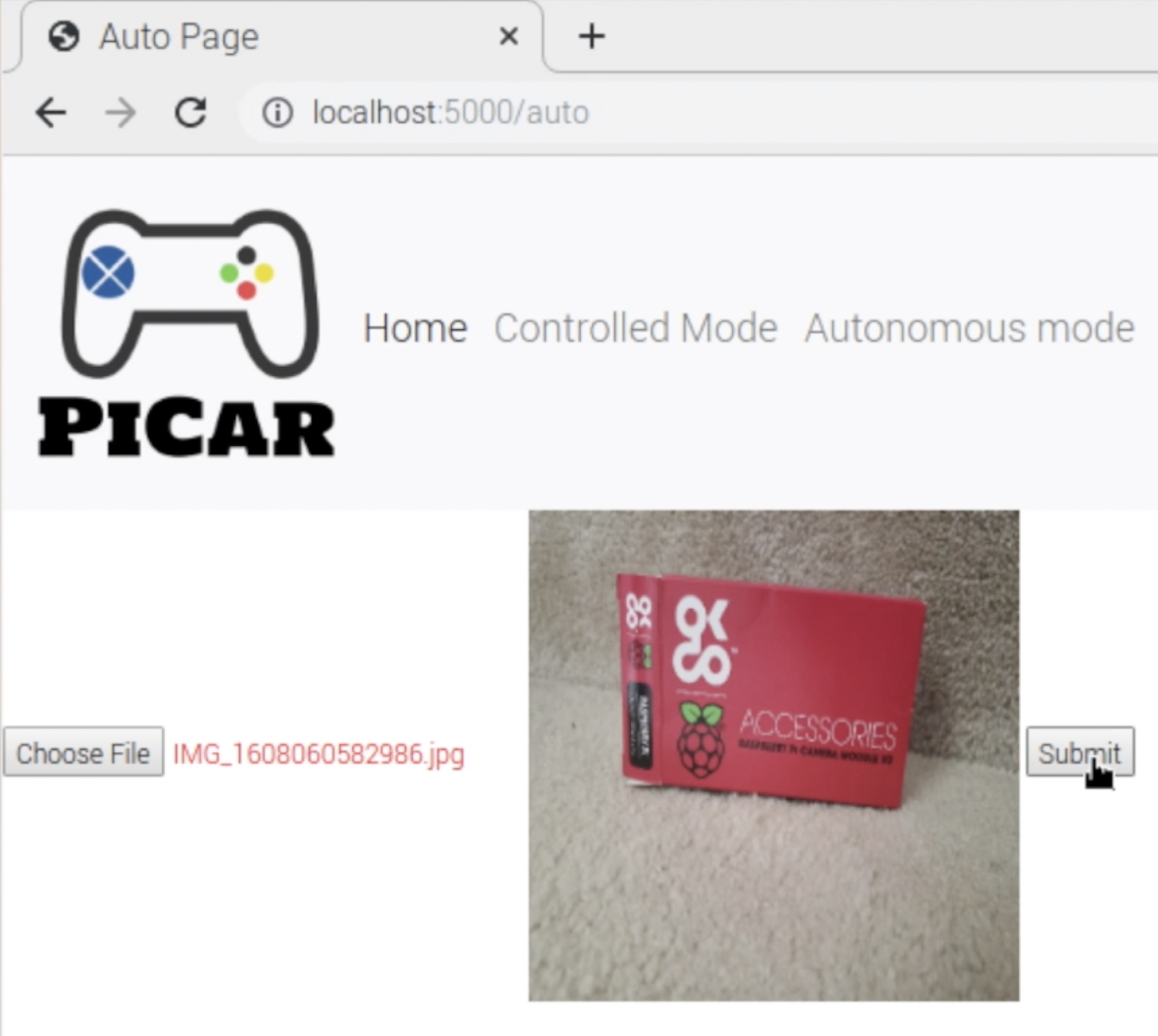
- @app.route('/auto'): return the autonomous page of the PiCar webiste namely auto.html
- @app.route('/robot_front'): entry point to command the server robot to move forward.
- @app.route('/robot_back'): entry point to command the server robot to move backward.
- @app.route('/robot_right'): entry point to command the server robot to move to the right.
- @app.route('/robot_left'): entry point to command the server robot to move to the leff.
- @app.route('/robot_stop'): entry point to command the server robot to stop.
- @app.route('/uploader'): given an image, this endpoint enables server robot to start auto search then returns ONLY after the item was found.
Camera Server
For control mode, the camera frame rate and latency is crucial. As the client relies on the website to control the robot remotely, any latency can affect the user experience. To resolve this issue and have a fast real time video feedback system, the control page relies on both the web server and camera server. These are two seperate processes running on the raspberry pi. Through context switching, each process will run as if it was the only one running thus decreasing any latency.
If the client decides to control the RPi server robot and navigates to the PiCar control page, the '\control' endpoint on the webserver will create a new process (if one already does not exists) of the camera server. Using Python os package, the webserver starts the camera server, puts it in the background, and save its PID. Later on, if the client switches mode (clicks on the autonomous tab), the webserver from the "/auto" endpoint kills the camera process. With limited resources (one camera), the server RPi cannot use the camera for both control and autonmous logic; therefore, the camera process gets killed which frees the camera for the auto mode logic. We have considered merging the logics for auto and control in order to eliminate the need of creating and deleting the camera process; however, due to the limited amount of time we had, we decided to have a working propotype that could always be improved.
The current camera server relies on the Python picamera library and uses a buffer to load different frames on a server. This server runs at port=8000 and exposes endpoints to retrieve frames as the server captures images from the RPi camera. This setup is very simple since we do not have to directly confifgure the RPi camera and can just rely on the picamera library after specificying options such as framerate. All of this code will then run in a particular process and the website can access the server by sending get requests to localhost:8000 which where the camera server is running.
Robot Control
In order to remotely control the robot, a class object named Robot_Control with methods that constitute the basic movements of the PiCar robot was created. This class uses the RPI.GPIO library to control the GPIO which will connect to the motor controller and essentially control the motors themselves. Since we did not want the robot to go full speed, as it drains the battery faster and makes it harder to drive, pulse width modulation (PWM) functions in GPIO were used to slow down to an acceptable level. Once configurations were set, methods were created in a modular fashion.
First was the method run(serv_leter, turn) which based on parameters, can control each of the motors to rotate clockwise/counterclockwise and also stop. That became the building blocks to make additional directional methods that would allow the robot to go forward, backward, left, right, and stop by executing run(serv_leter, turn) for both motors consecutively. Each of the methods that execute these movements were named by their respective direction.
It was initially planned that besides autonomous, only those methods would be created. In testing, however, we soon realized that since the motors are not calibrated to operate at the same inputs when a directional method is executed, one motor would rotate faster than the other, causing improper movement. To overcome this issue, new methods were created such that it would still execute the methods as usual, however, it would only run for a specific time so that the robot would perform the correct, albeit short, movement. Although this does limit movement to some degree, it was decided that there was a better approach.
The last method created was autonomous(straight_time, turn_time). This method causes the robot in a rectangular spiral. Ideally, we want the robot to scan the area, determine whether the target is in the vicinity, and then move on to another location. Because of this, the method only performs one-directional movement per function call. Using an attribute of the class movement_counter, the robot keeps track of its previous movement by looking at the counter, making the approximate movement based on that value, and then increments the counter to signify what the previous move was. The parameters, straight_time, turn_time are set based on its search area and decrements the straight time so that when it has covered the entire search area, that function will not execute any movement and stay in place. Testing of this method was done in another python script before it was added to the class as a method.
Robot Detection
Robot_Detection, another class object, was made so that when autonomous mode is chosen, the robot itself can determine whether the target is in the area or not. Robot Detection was made so that multiple targets can be searched for but for demo purposes, only a single target was searched for. Additionally, Robot_Detection uses Robot_Control to facilitate the movement of the robot itself as opposed to simply reusing the same command.
Robot_detection uses the image uploaded from the website and compares it with its surroundings with image recognition from OpenCV. First, the image of the target is located in the Raspberry Pi with the method load_images() where it is decomposed into four separate variables: its name, the image file itself, the descripers, and keypoint detectors of the photos (the last two are generated using OpenCV’s Oriented FAST and Rotated BRIEF (ORB) algorithm).
Once that is generated, the robot will take a photo of the area and then compare it with the target’s photo using the method findID(image). In that method, the image keypoint detectors and descriptors are generated with ORB. The image’s descriptors and target descriptors’ are then compared with another matching algorithm that generates a single value of their similarities. If a certain comparison value is greater than a specific threshold value, it is determined that the image is found, and the name of the image is returned. If not, A string, “Object Not Found” is returned”. If multiple targets are above the threshold value, the one with the highest value is selected. This threshold value, as we found through testing, varies mainly on the external lighting of the area, and as such was changed as needed.
These two methods are then used in the method start(). load_images() is initially executed, with the straight_time and turn_time set before run. Then a continuous loop begins to search for the image where the Camera takes five photos of the same location and uses findID() to see if the target is in the line of sight. If the target is recognized, the loop is broken and the program terminates when sending a signal to the client that the object is found. If not, autonomous() is called to begin moving the robot to a new location where it continues to do so until the object is found. Print Statements were also embedded into the detection for debugging purposes as well as give the server terminal a near real-time update of the robot.
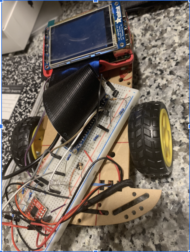
Hardware
With the exception of the Camera Setup, the Hardware remains nearly identical to one found in lab 3 of the FAll 2020 ECE 5725 course. Although, this shall be reiterated, please see this pdf report for more detailed information.
Camera Setup
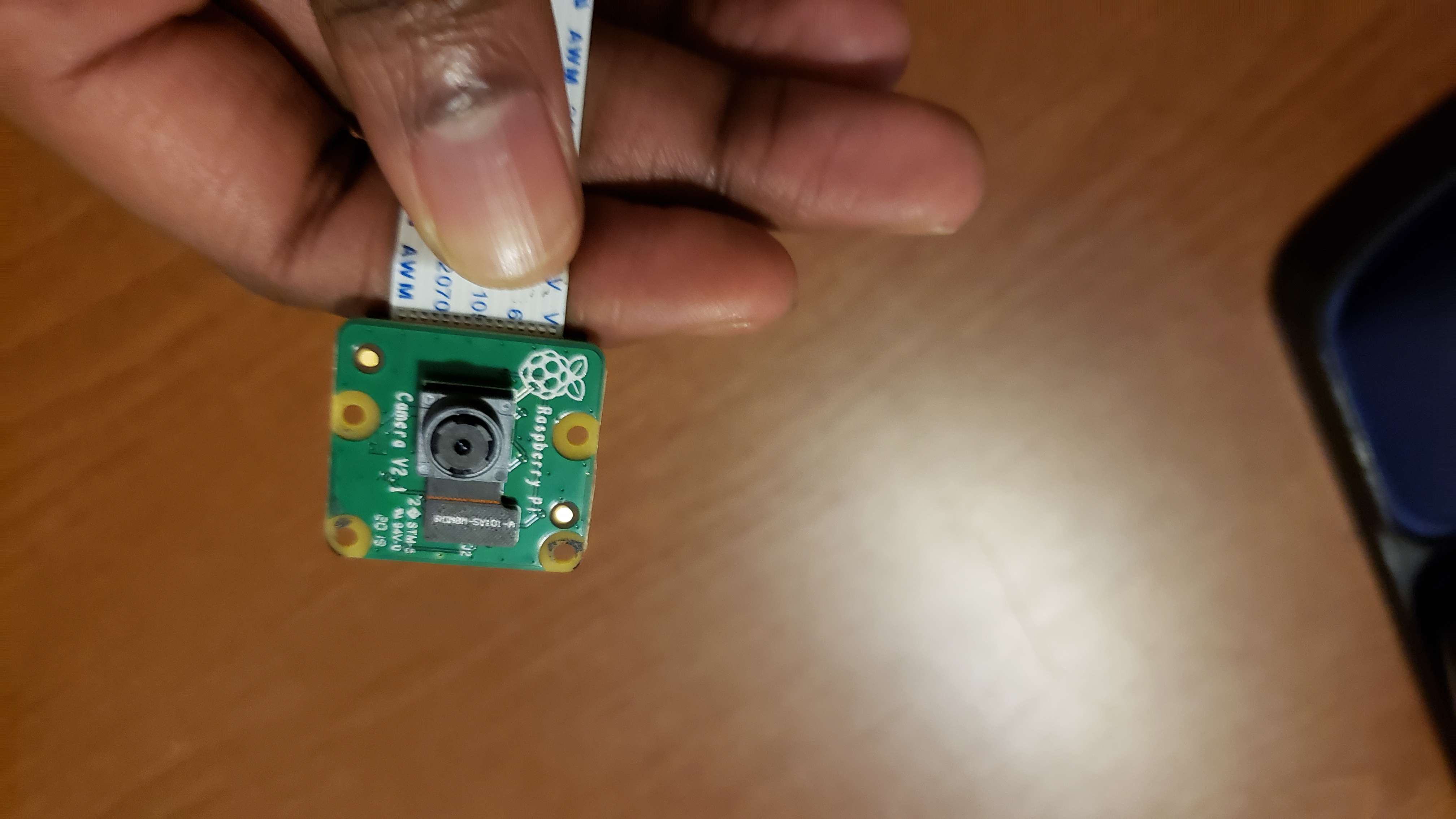
The PiCar uses a V2 raspberry pi camera module that is mounted on the front of the robot. This camera was chosen for two reasons. First, was that with the $100 budget constraint, it provided the necessary specifications while still being cheap. Secondly, since the camera is an official Raspberry Pi accessory, there was painless integration with the robot and raspberry pi. Even more so, we were about to take advantage of the PiCamera’s python library, which makes programming easier. Earlier attempts used the OpenCV libraries to take the images resulting in slow capture times. Switching to the PiCamera libraries for photo capture and then using OpenCV image for computation yielded not only better performance, but also allowed easier use with the webserver.
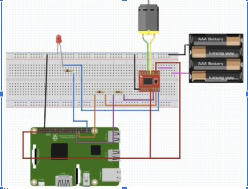
Motors Setup
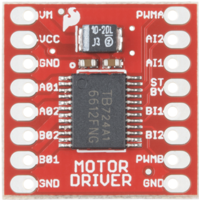
The motor controller, Sparkfun TB6612FNG dual-channel motors were used to control the two motors, acting as the adapter from the GPIO outputs to the inputs of the DC motors. The inputs that control one a motor were labeled “PWM A, INA2, and INA1”, with the other motor inputs being labeled as to its “B” variants. The motors themselves are 6v DC motors. Since these motors run on 6V, an external battery pack is used as the voltage rail and is connected to the VCC input of the motor controller.
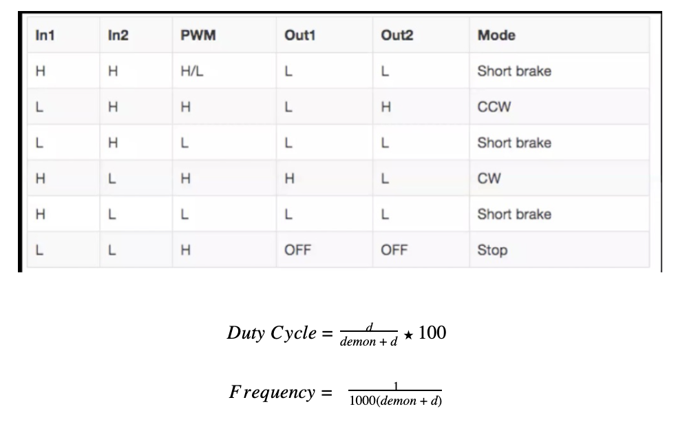
IN1 and IN2 control the direction in which the motor spins where PWM controls the speed. That is due to the fact the motor controller looks at the duty cycle of PWM and determines the necessary speed. A duty cycle of 1 signals that the motor must go full speed, with a duty cycle of 0 means it does not move. Anything in-between means a speed proportional to its duty cycle.
Results/Conslusions
After hours of debugging, we were able to complete all of our initial goals. While we largely met the goals outlined in this project, there were some troubling shootings. We were successfully able to remotely control the robot through a website, and more importantly, connect to each other's Raspberry Pi’s, however it was not initially planned that tunneling was to be used. We would also be able to develop an image recognition algorithm that had relatively low false positives and a robot that can search for the object itself; yet, lighting played a much more significant role and expected and caused both team members to vary the algorithms ‘aggressiveness’ based on that. There were major latencies in the camera in initial testing, but it got resolved as we adapted the code. Additionally, the miscalibrations of the motors made movement an at first problem - something that we did not expect seeing that lab 3 provided a basic introduction to motor control. Nevertheless, a solution was found. In short, our project, PiCar, is able to provide remote and autonomous control as intended.
Appendices
Future Work
If this project was to be continued, certain aspects of this project would be improved. Firstly, a feedback system for the motors would be implemented to help with the miscalibration of the motors. This was an expected issue we encountered and although the solution was always clear to us, we did not have enough time to design and install.
Secondly, more time would have been used to find a camera that is higher resolution but still cheap. One of the factors that determine the performance of image recognition is the quality of the photo itself. Having a better quality camera would reduce the false positives in the PiCar.
Lastly, another possible improvement is merging the logic for control and autonomous mode and adding more “good to have” features . As of now, the server has only one camera so we created and killed the camera process as different modes asked for the camera. Although this is not ideal, it gave us the prototype we needed. However, allocating and deallocating the process is wasteful and can be improved if we create maybe one instance for the camera class that can be passed around depending on which tab is open. Other improvements involve giving the user more control or improvement on the UI. For example, one is adding the ability to increase the speed by adding a slider HTMLelement.
In conclusion, there are multiple ways we can improve PiCar; however, given the timeline, we were able to achieve all our goals; however, future works can always build on top of this prototype.
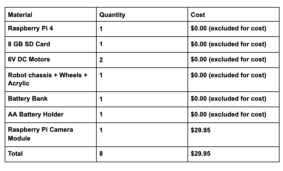
Budget
References
- https://unix.stackexchange.com/questions/46235/how-does-reverse-ssh-tunneling-work: contains an explanation on ssh tunneling and which commands to use and why.
- https://html5up.net/: contains templates on how to create static sites
- https://www.raspberrypi.org/forums/viewtopic.php?t=89834: advice on how to deal with image detection of dark-lit places.
- https://www.raspberrypi.org/documentation/usage/gpio/python/README.md: documentation of the GPIO library.
- https://docs.opencv.org/master/d1/d89/tutorial_py_orb.html: documentation on ORB
- https://docs.opencv.org/3.4/dc/dc3/tutorial_py_matcher.html: documentation on Feature Matching.
- https://www.youtube.com/watch?v=nnH55-zD38I: a video showing image recognition in action.
- https://randomnerdtutorials.com/video-streaming-with-raspberry-pi-camera/: explains how to setup RPi camera
Code
Our full repository of source code for PiCar can be found here
App.py - handles endpoinnts and starts camera server.
robot_control.py - controls the robot movement.
robot_detection.py - starts the camera and runs search algorithm.
server.sh
client.sh